
If you’re building an emulator, you can hardly avoid relying on automated tests to prevent regressions. A common approach is unit tests. They verify individual parts of your code in isolation and therefore need to be tailored to the specific emulator. To complement that, integration tests validate the behavior of the emulator as a whole.
Test ROMs as integration tests
A particularly interesting form of integration testing is test ROMs. They run directly on the emulated platform and probe specific behavior. You could say they test the hardware “from the inside out.”
A Game Boy test ROM could, for example:
- examine timer behavior by timing the exact cycle
that increments the
TIMAregister. - check PPU mode 3 duration for different
SCX, window, and sprite configurations. - demonstrate the effects of the
DIVregister on the APU.
Well-known test suites
There are entire collections of Game Boy test ROMs, called test suites. One of the best known is the Mooneye Test Suite, developed by Joonas Javanainen (Gekkio). Also worth your time are Lior Halphon’s SameSuite and Matt Currie’s Mealybug Tearoom Tests. There are plenty of others as well, too many to list here.
I’ve put together a collection of test suites by various authors in one of my GitHub repositories.
Pros and cons of test ROMs vs. unit tests
Compared to unit tests, the barrier to entry for Game Boy test ROMs is significantly higher. As integration tests, they are more involved to run: You have to start the full emulator, load the test ROM and execute it, and then determine the outcome through an appropriate evaluation (e.g., comparing screen output, memory contents, or CPU registers). Creating test ROMs is also more complex: you need a dedicated toolchain, compile ROMs separately, and they’re typically written in assembly — not exactly a mainstream language.
On the other hand, test ROMs come with clear advantages:
- They are independent of the emulator’s implementation. Any emulator for the platform can use them.
- They run on real hardware, so anyone can verify correctness there.
Developing Game Boy test ROMs
You’ll need a suitable toolchain to develop Game Boy test ROMs. My favorite is RGBDS combined with a Makefile. RGBDS is tailored to Game Boy development and includes an assembler, linker, and utilities for graphics conversion and header patching. For small projects, rgbds-live even lets you write and try code directly in the browser.
Popular alternatives to RGBDS include WLA DX (a cross-assembler for various CPUs) and GBDK (a C toolchain for Game Boy software).
While RGBDS and WLA DX are assembly-only, GBDK also supports C. For folks new to Game Boy development, GBDK might be the easier path. However, when using C you don’t directly control which CPU instructions the compiler emits. For test ROMs that often rely on cycle-exact timing, assembly is the better choice.
Running on real hardware
To try your software on a real Game Boy, you’ll need a suitable flash cartridge. I currently use the EZ-FLASH Junior, which you load via microSD card. There are other options of this type as well. A quick search for “Game Boy cartridge adapter” on Google or Amazon will turn up viable choices.
Almost all of these adapters can host multiple ROMs at once. On boot, you choose the ROM to run from the Game Boy’s menu.
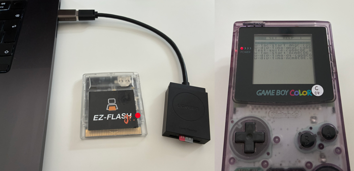
Laptop with microSD card, EZ-Flash Junior, and the selection menu on a Game Boy Color
A simple example test ROM
To illustrate, let’s look at a (very simple) test ROM for
DIV timing.
It verifies the cycle of the very first DIV increment after a DIV reset,
and consists of three parts:
- Initialize VRAM and BGP
- Run the actual test
- Display the result (✓ / ╳)
To try it out, copy the code from Listing 1 and run it on
rgbds-live
(replace the prefilled main.asm entirely).
To make the test fail,
you can change the numeric value in line 48 or 54, for example.
|
|
Listing 1: a simple example test ROM to try on rgbds-live
Implementing a test framework
As you can see, the test ROM above is largely initialization and result display. The actual test logic takes about 20 of the roughly 100 lines. In a full test suite, this boilerplate code would repeat in every single test ROM. It’s therefore worth moving those parts into a shared test framework that each test ROM can include.
Typically, a test ROM includes the framework code before its own test code. The framework handles program startup and initialization and provides helpers commonly used across the suite. The test suites mentioned above — Mooneye Test Suite, SameSuite, and Mealybug Tearoom Tests — use this approach.
Evaluating the result in the test ROM
If we pull initialization and result display out of the example test ROM into
a test framework,
we’re left with Listing 2.
After initialization by the framework, the test ROM runs its checks as usual.
It also still performs its own evaluation:
on failure it calls the TestFail routine to finish
(lines 16 and 23),
and on success it calls TestSuccess
(line 26).
|
|
Listing 2: code of the example test ROM with the test framework included
The test framework (Listing 3) provides program start and initialization
as well as the TestSuccess and TestFail routines.
It also takes care of displaying the result.
This makes individual tests leaner and easier to maintain. At the same time, the test ROM remains completely free in how it evaluates its results and can abort early if needed (“fail fast”).
The Mooneye Test Suite is implemented this way.
|
|
Listing 3: the test framework used by the example test ROM
Evaluating results in the test framework
Our example test ROM only checks two data points:
the value of DIV immediately before and exactly during
its first increment.
That’s manageable to evaluate inside the ROM itself.
But if a test produces hundreds or even thousands of data points,
doing the comparison in the ROM quickly becomes unwieldy.
An alternative is to perform the comparison in the test framework. To do that, the framework reserves a region in WRAM. Each test ROM stores its measured values there and also provides the expected results. The framework compares both and then shows pass or fail.
The advantage is that test ROMs can become even slimmer, since they no longer have to evaluate their own results.
The downside is that the test must always run to completion before you get an outcome. A “fail fast” approach isn’t possible, as that would require evaluation within the ROM.
This is how SameSuite and Mealybug Tearoom Tests operate.
Using test ROMs in automated integration tests
To run the example test ROM as an automated integration test, you load it into the emulator under test and let it run for a certain time. After that, you verify the result automatically. To make this reliable, two questions need answers:
- How long does the example test ROM need to run before a result is available?
- How is the result checked automatically — i.e., pass or fail?
Of course, these questions apply to every test ROM, not just our example.
Current convention
Mooneye Test Suite, SameSuite, and Mealybug Tearoom Tests all follow the same convention here. The Mooneye Test Suite likely led the way, originally being part of the Mooneye GB emulator.
-
A test is considered complete once the instruction
ld b, bexecutes. Since that instruction has no effect other than taking one cycle, it’s not used in normal code. -
A passing test is signaled by a specific set of CPU register values — a slice of the Fibonacci sequence:
- B = 3
- C = 5
- D = 8
- E = 13
- H = 21
- L = 34
If a test finishes with different values, it is considered failing.
Our example test ROM adheres to this convention once you adjust the test framework as shown in Listing 4.
|
|
Listing 4: framework snippet to signal the test result
Visual/analog test results
Not every test ROM can evaluate its own result. A classic example is video output: the test ROM can render a picture, but it can’t verify whether it’s displayed correctly.
In such cases, the test ROM simply signals completion with ld b, b.
The actual evaluation is done by the integration test harness.
To do that, the test ROM is bundled with a reference screenshot,
which is compared to the emulator’s actual output.
There’s also a convention for the colors in such screenshots:
- DMG screenshots use these colors:
#000000,#555555,#AAAAAA,#FFFFFF - CGB screenshots convert 15-bit CGB colors to 8-bit per channel:
(X << 3) | (X >> 2) - “Non-CGB mode” screenshots use these colors:
- BGP:
#000000,#0063C6,#7BFF31,#FFFFFF - OBP:
#000000,#943939,#FF8484,#FFFFFF
- BGP:
Conclusion
- Test ROMs are ideal as integration tests for emulators: They verify the behavior of the emulated hardware and run both on emulators and on real hardware.
- Compared to unit tests, they’re more effort to create and run, but once written they can be reused across emulators.
- For precise timing, assembly is the better choice over C.
- A test framework cuts boilerplate and makes it much easier to build larger test suites.
- With tools like RGBDS, WLA DX, or GBDK and a suitable flash cart (e.g., EZ-FLASH Junior), you can cover everything from development to testing on real hardware.